What changes should I make? And how to connect unipolar stepper motor to L298. I am using Atmega 32 uc and codevision compiler. I am getting spikes on output pins of L298. Pin no.16 (OSC) = getting saswtooth waveform (2.5v clamped). On pin no 8 and 5 (INH1, INH 2) = getting high frequency pulses. Pin no 7 (c)= getting 5v pulses(I think this is normal) 4.

Pin no.6 (B) = getting 10v clamped pulses. After interfacing the motor I observed the signals on input and output of IC on CRO. I connected Enable A and Enable B pin of L298 to VCC i.e.Įnable pin of L297 to 5 V. I have attached the circuit diagram below.

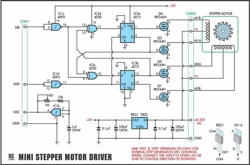
I have use l297 and l298 IC for controlling as well as driving the motor. I want to interface stepper motor but it is not rotating (My stepper motor's specification is, unipolar stepper motor, Torque = 3.17 kg-cm, current/phase = 0.4 Amps, resistance/phase = 30 ohms, voltage = 12v). Hi everybody, I am currently working on solar tracking system. Now as shown in the circuit diagram the 555 circuit here is to generate clock or the square wave. The figure shows the circuit diagram of two stage stepper motor driver. Stepper Motor Driver Circuit Diagram and Explanation. Vref is the input into L297? How come you say 'Vref of a driver chip is the output, that you can use your ADC to measure this voltage'.


 0 kommentar(er)
